

In the power transmission and distribution system, transformer parallel operation is a common and important operation mode, which can improve power supply reliability, optimize load distribution, and make full use of equipment capacity. Especially for industrial and commercial scenarios that require stable power supply, mastering the conditions and reasonable operation modes of transformer parallel operation is crucial to ensuring safe and efficient operation. As a professional manufacturer of power transmission and distribution equipment, JINSHANMEN TECHNOLOGY CO., LTD provides professional technical support for transformer parallel operation while producing high-quality transformers. The company mainly produces oil immersed power transformers, dry-type power transformers, oil immersed three-dimensional coiled power transformers, dry-type three-dimensional coiled power transformers, mining explosion-proof dry-type transformers, mining explosion-proof mobile substations, amorphous alloy power transformers, on load capacity regulating power transformers, locomotive dry-type transformers, as well as prefabricated substations, modular substations, wind energy box type substations, high and low voltage switchgear and other transmission and distribution equipment.
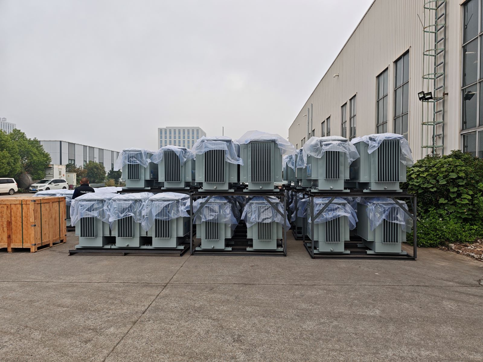
I. Basic Conditions for Transformer Parallel Operation
To ensure the safe, stable and efficient parallel operation of transformers, four core conditions must be met. If any of these conditions are not satisfied, it will lead to circulating current, uneven load distribution, increased energy loss, and even serious safety accidents such as transformer burnout. The 3 phase 100 kva transformer, which is widely used in small and medium-sized industrial and commercial projects, also needs to strictly abide by these conditions when operating in parallel. The same applies to the oil immersed power transformer, which is widely used in outdoor and large-capacity power supply scenarios.
1. Identical Connection Groups
The connection group determines the phase relationship between the primary and secondary voltages of the transformer. If two transformers with different connection groups are connected in parallel, a large voltage difference (usually up to 51.8% of the line voltage) will appear in the secondary circuit. Due to the small internal resistance of the transformer, a circulating current several times the rated current will be generated instantly, which will rapidly overheat the winding and burn out the transformer. This is the most critical condition for transformer parallel operation and must not be violated. Whether it is a 3 phase 100 kva transformer or an oil immersed power transformer, the consistency of the connection group must be checked first before parallel operation.
2. Equal Voltage Ratio
The voltage ratio (transformation ratio) refers to the ratio of the rated voltage of the primary side to the secondary side of the transformer. If two transformers with different voltage ratios are connected in parallel, a steady circulating current will be generated in the secondary winding even when they are no-load. This circulating current will not only increase the no-load loss of the transformer but also occupy the equipment capacity, reducing the load-carrying capacity of the transformer. According to relevant national standards, the allowable difference of the voltage ratio of parallel transformers shall not exceed ±0.5% (when the tap switch is in the same position). For example, when two 3 phase 100 kva transformers are connected in parallel, their voltage ratios must be adjusted to the same value to avoid circulating current. The same requirement applies to the parallel operation of oil immersed power transformers.
3. Equal Percentage of Impedance Voltage
Impedance voltage (also known as short-circuit voltage) is an important parameter reflecting the impedance characteristics of the transformer winding. The load distribution of parallel transformers is inversely proportional to their impedance voltage percentage. If the impedance voltage percentages of two transformers are different, the transformer with a smaller impedance voltage will bear more load, while the transformer with a larger impedance voltage will be underloaded, resulting in the waste of equipment capacity. Generally, the allowable difference of the impedance voltage percentage of parallel transformers shall not exceed ±10%. In practical application, we can adjust the tap position of the transformer to make the impedance voltage percentage tend to be consistent, so as to ensure the reasonable distribution of load. This adjustment method is also applicable to the parallel operation of 3 phase 100 kva transformer and oil immersed power transformer, which can give full play to the capacity of the equipment.
4. Capacity Ratio Not Exceeding 3:1
The capacity ratio of parallel transformers should generally not exceed 3:1. This is because the impedance value of transformers with different capacities differs greatly, which will lead to uneven load distribution. In addition, from the perspective of operation and maintenance, small-capacity transformers cannot play an effective standby role when the capacity ratio is too large. However, if both transformers do not exceed the rated load during operation, the capacity ratio can be greater than 3:1. It should be noted that under normal circumstances, the impedance voltage of a large-capacity transformer is smaller than that of a small-capacity transformer, and the impedance angles of the short-circuit impedance of each transformer should be equal to ensure that the secondary current is in the same phase and the equipment is used reasonably.

II. Rational Configuration of Transformer Parallel Operation Modes
Transformers will generate energy loss during operation, and the more transformers connected in parallel, the greater the total loss. Therefore, the number of parallel transformers should be adjusted according to the actual load change in the power supply system. The core of rational configuration is to minimize the total loss of the transformer and realize economic operation. This principle is equally applicable to the parallel operation of 3 phase 100 kva transformer and oil immersed power transformer, which can effectively reduce the operation cost of the power supply system.
1. Types of Transformer Losses
Transformer losses are mainly divided into two types: iron loss and copper loss. Iron loss is almost unchanged during normal operation, also known as constant loss; copper loss changes with the square of the load current, also known as variable loss. The efficiency of the transformer is the highest when the constant loss is equal to the variable loss, which is the most economic operation state of the transformer. In addition, transformer losses can be divided into active loss and reactive loss. Reactive power consumed by equipment is supplied by the power system. The existence of reactive power will increase the current in the system, thereby increasing the active loss of the power system.
2. Determination of Parallel Transformer Quantity
When determining the number of parallel transformers from an economic perspective, it is necessary to consider both active loss and reactive loss, and convert reactive loss into active loss through the reactive economic equivalent (kq, unit: kW/kVar). For substations, kq is generally 0.02 ~ 0.15. The specific number of parallel transformers is determined according to the following two situations:
(1)Transformers with the Same Model and Capacity
When the parallel transformers have the same model and capacity, the number of operating transformers under different load conditions can be determined by the following formula: When the load increases to S > n×Sn, it is more economical to add one more transformer to the parallel operation; when the load decreases to S < (n-1)×Sn, it is more economical to cut off one transformer from the parallel operation. Among them, S is the total load capacity of the transformer (kVA), Sn is the rated capacity of each transformer (kVA), and n is the number of operating transformers. For example, when multiple 3 phase 100 kva transformers are connected in parallel, the number of operating transformers can be adjusted according to the change of total load to ensure economic operation.
(2)Transformers with Different Models and Capacities
When the parallel transformers have different models and capacities, their iron losses are not necessarily equal, and the load distribution is more complex, so it is difficult to determine the number of operating transformers by a single formula. The practical method is to draw the curve of the total loss of each transformer and the total loss of multiple parallel transformers with the load, and determine the number of transformers to be put into operation according to the curve (the number of transformers corresponding to the lowest loss under the current load is the most reasonable). In addition, the regulations stipulate that to reduce the number of operations in a day and night, the shutdown time of the transformer shall not be less than 2 ~ 3 hours. This method is also applicable to the parallel operation of oil immersed power transformers of different models and capacities.
III. Conclusion
The safe and economic parallel operation of transformers is the key to ensuring the stable operation of the power transmission and distribution system. It is necessary to strictly abide by the four core conditions of identical connection groups, equal voltage ratio, equal percentage of impedance voltage, and capacity ratio not exceeding 3:1. At the same time, the number of parallel transformers should be reasonably configured according to the load change to minimize energy loss. As a professional manufacturer of power transmission and distribution equipment, JINSHANMEN TECHNOLOGY CO., LTD provides high-quality 3 phase 100 kva transformers, oil immersed power transformers and other products, and provides professional technical guidance for the parallel operation of transformers, helping users achieve safe, efficient and economic power supply.