

Below is an analysis of the secondary circuit for transmitting transformer oil temperature and winding temperature to the background. Specific analysis and troubleshooting can be carried out according to this secondary circuit (of course, the specific situation requires the corresponding secondary circuit).
I. On-Site Transformer Oil Temperature Gauge and Winding Temperature Gauge
As shown in Figure 1 and Figure 2, the oil surface thermometer can output both Pt100 resistance signals and 4-20mA small current signals, while the winding thermometer can only output 4-20mA small current signals. Additionally, when the thermometer outputs 4-20mA small current signals, it needs to be connected to a 220V AC power supply. In this station, 4-20mA small current signals are used to input into the measurement and control device.
Figure 1 Oil Surface Thermometer
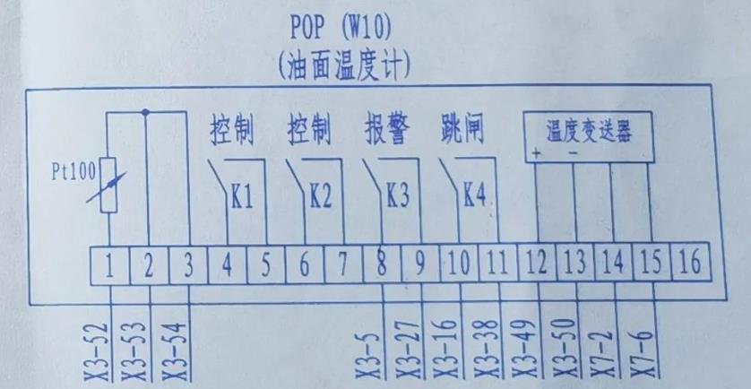
Figure 2 Winding Thermometer
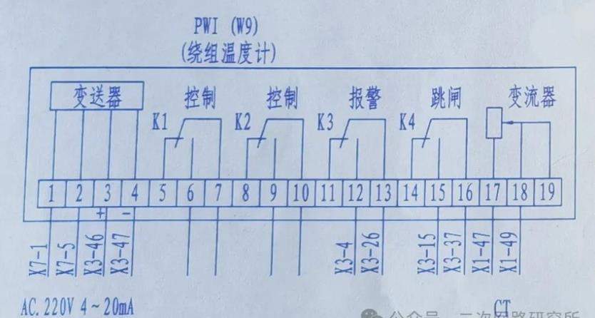
The wiring of the oil surface thermometer and winding thermometer are led to the transformer body terminal box, and then these small current signals are led to the transformer measurement and control device via cables.
II. Small Current Signal Input of Transformer Measurement and Control Device
As shown in Figure 3, the measurement and control device can input both Pt100 resistance signals and 4-20mA small current signals.
Figure 3 Small Current Input Circuit of Transformer Measurement and Control Device

After connecting the 4-20mA small current signal to the transformer measurement and control device, it is necessary to determine the measurement range of the transformer oil surface temperature gauge and winding temperature gauge, and inform the background manufacturer to configure certain coefficients so that the corresponding temperature can be displayed on the background.